Propeller design using catia v5

Published on . Written by

Propeller design using CATIA V5
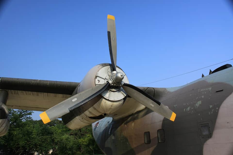
A propeller is a distinct type of fan that translates rotational motion into thrust by producing a pressure difference in the nearby fluid. Typical fans and propellers have the same physics, yet a fan is generally still, while a propeller causes the object to be in motion. Propeller is a main component in several industrial designs regarding rotating machinery.

Read more..
CATIA stands for Computer-Aided Three-dimensional Interactive Application. It's a marketable CAD software designed for physical modeling in various productions including Mechanical and Aerospace


Skyfi Labs Projects
Design parameters can influence the performance of the propellers or fans.

  • The Number of Blades: Increasing the number of blades will truly reduce the effectiveness of the propeller but with a higher number of blades, there is a better distribution of thrust.
  • The Diameter: The diameter of the propeller has an important impact on its efficiency. Larger propellers can create additional power and thrust on a larger volume.
  • The velocity of Flow: The presumed velocity of the fluid flow, whether it be air or water, is another important variable to consider. This force, along with the velocity of rotation (RPM) determines the pitch distribution of the system. Large propeller designs can become less effective operating at the axial velocity. The most efficient designs are those which maintain a pitch to diameter ratio of 1:1.
  • Fluid Flow Density: While the actual density of the fluid does not affect the efficiency of the system, it does play a role in defining the shape and size. For example, an air propeller used for planes and drones will have a bigger face than its aquatic counterparts, as the fluid density is less.
Procedure:

  • Go to start-select mechanical design- wireframe and surface design
  • Select line definition- point direction- Give input value for start 0 mm and end 200 mm-then click OK
  • Click on translate option- choose element as line 1- direction z-axis- distance 10 mm.
  • Click on the rotate definition- definition mode as axis angle- select element as translate 1- select Axis as z-axis- give input for angle as 8 degree- click OK
  • Select the centreline - right click and then hide the line.
  • Now select line definition- select point 1 and point 2- click OK
  • Connect the end 2 points using connect curve option by setting continuity as curvature- select points
  • After connecting endpoints go to connect the curve option and select reverse direction
  • Give input values for tension as 2 and 1.3 respectively- click OK
  • Click fill command -Select the contour lines
  • Now go to start - select mechanical design- click part design.
  • Select xz plane- enter sketch- create a circle for propeller center by giving the desired radius.
  • Go to pad definition- use mirror extent.
  • Select the centerline of circle and propeller- click thickness definition- select first offset as 3mm-click ok
  • Select the upper curved surface of the propeller and click the fill option.
  • Use circular pattern definition for creating more propellers- choose thick surface-click OK.
  • The propeller is ready.


Kit required to develop Propeller design using catia v5:
Technologies you will learn by working on Propeller design using catia v5:


Any Questions?


Subscribe for more project ideas