Gear train design using Autodesk Inventor

Published on . Written by

Gear train design using Autodesk Inventor

CAD (Computer Aided Designing) is the process of making a 2D or 3D design of a product using the design software which makes designing and upgrading the product design faster compared to the manual drawing.


Skyfi Labs Projects
In this CAD project, we are going to use Autodesk Inventor software to design a Gear train assembly. Autodesk Inventor is a 3D CAD software that enables the user to design, simulate, visualize and create documentation for a product.

Read more..

SLNOTE
Without gears the world will become motionless, gears are used in almost all the moving parts to transmit the motion from one part to another. For example, gears are found in - the gearbox, power transmission from the engine to the rear wheel, differentials, etc.

The main aim of the gear train is to provide the optimum torque without any slippage in the transmission of motion from one gear to another.


SLLATEST
Procedure to design a gear train using Autodesk Inventor:

  1. Install the student version of the Autodesk Inventor in your Laptop/PC.
  2. After starting the software you will see a window which shows assemble, part design, drawing, presentation, etc. Click on assembly.
  3. Now click on design which is present in the menu bar.
  4. Select the gear option you will find three different gears - spur gear, bevel gear, worm gear, etc.
  5. Click on which gear you want to design, the system will ask you to save the file first before you start.
  6. After that, a screen will pop up which will ask you to give the dimensions of the gear like, number of teeth, gear ratio, the diameter of pitch, helix angle, pressure angle, etc.
  7. Now click on preview that shows the dimensions, teeth mesh, pinion and rack mesh, gear and rack mesh, etc.
  8. Under teeth mesh option  - there will be one option called animation forward which gives you the animated view of the gears.
  9. Under gear 1 and gear 2 keep both the options as component. Then click OK.
  10. Now you will see the gears in the worksheet.
  11. Similarly, design and add the gears as per your dimensions.
  12. Under assembly tab click constrain and go to motion and give the gear ratio as per your wish (1/3) and select the bigger gear as gear 1 and smaller gear as gear 2.
  13. Select the direction of rotation and click apply and ok.
  14. Now click on and hold the gear and rotate it now both the gears will rotate. If any slippage happened, change the teeth and mesh distance and try again.
  15. Similarly, try to design the other gears such as bevel gear and worm gear.
  16. You can also check the speed, power, or torque produced by the gear combinations.
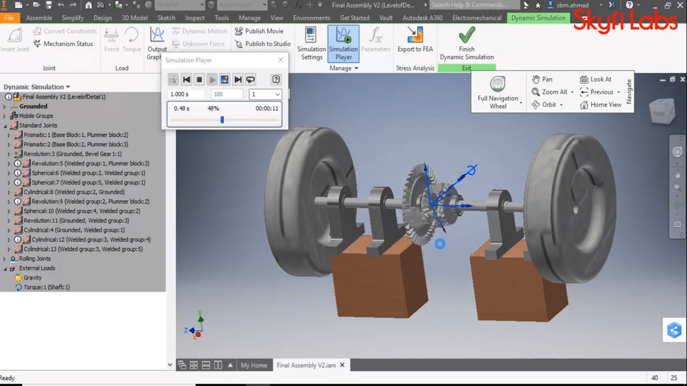
  17. Perform the dynamic simulation which is under the environment tab and select the simulation which you want to perform.
  18. Now a simulation tab will open which allows you to give the values to perform the simulation.
Using the Autodesk inventor software you can make various CAD drawings easily. You can download the software and install it for free. For more information refer the below link - https://www.skyfilabs.com/online-courses/gear-train-design?v1


SLDYK
Kit required to develop Gear train design using Autodesk Inventor:
Technologies you will learn by working on Gear train design using Autodesk Inventor:


Any Questions?


Subscribe for more project ideas