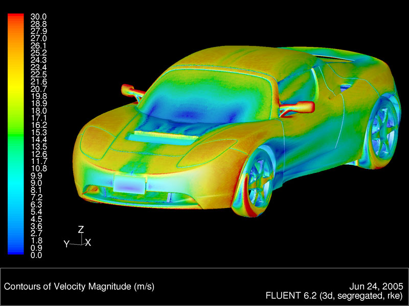
CFD Analysis of full car

Published on . Written by

CFD of full car

Project Description


Skyfi Labs Projects
A decade ago aerodynamics was insignificant among commercial vehicle manufacturers. It had its application in aerospace industry and F1 or any other racing. Today more and more companies are focusing on aerodynamics of even the mid-range road vehicles. Researches have concluded that with proper optimization of aerodynamics, fuel efficiency improves.

In this project you will learn to use SIM SCALE, an online tool for performing the CFD analysis of a formula style racing car. SIM SCALE allows us to upload and perform analysis online so that we do CFD on even low end computers.

Read more..

SLNOTE
Project Implementation

Prepare a CAD model of a formula style car using any CAD software like Solidworks or Catia etc. Save it in STEP, IGES or any supported format. If you wish to only perform the analysis then download a CAD model from www.grabcad.com. The car should have wheels, front and rear wings. This analysis requires only half of the car to perform CFD.

Open SIM SCALE IN chrome by going to their website. Create an account and start a new project. Upload the CAD model of the half-car.

Create a simulation and select in-compressible flow because for our analysis the Mach Number is lower than 0.3. First step is to create a mesh and refine it, then define the initial conditions and boundary conditions. After that setup the simulation and run it. Final step will be the post processing.

While generating the mesh, choose Hex dominant primitive. Use the k-omega SST turbulence model. Go to geometry primitives and increase the size of the Background Mesh Box. Keep it at-least 3 car length behind your model, at-least 1 car length in the front side and top.

The symmetry wall should be exactly along where the car is cut in half. Choose a material point inside this box. Make more Cartesian boxes which only cover the wheels and wings. Do this because the mesh size will be finer here. Add mesh refinements.

Choose the type of refinement that you need to add. For example, for surface refinement select car body, front and rear end plates, diffuser and driver. Choose the level of refinement based on how important the wind surface interaction is at that place. Choose higher level for higher level of refinement.

For wheels add a rotating zone refinement and change create cell zone to true. For the whole car surface add a boundary layer refinement. Add a region refinement for the Cartesian boxes.


SLLATEST
Choose their level of refinement accordingly. Keep it high for more turbulence regions. Start the mesh operation after that. The rotating wheel refinement is for wheel air interaction.

Once the meshing is done you move onto the simulation setup. Be sure that the mesh is proper before starting this. Firstly in Materials select Air and save. Choose all the Cartesian boxes as the volumes.

Then we give the initial conditions. Don’t change the the values of pressure and velocity. Set k to 0.06 and Omega to 44.7. Now set the boundary conditions - 

  1. The front surface of the bounding box as inlet and velocity to 20 m/s.
  2. The rear end of the bounding box as pressure outlet.
  3. The sides and top as wall and velocity to slip.
  4. Set the symmetry wall as Symmetry.
  5. Set the floor to moving wall with velocity 20m/s.
  6. Add another condition of wall type where you select the entire car except the tire. 
Set another boundary condition of type wall and keep velocity as rotating wall. Set the origin value as the coordinates of the center of the wheel and choose the tire under assignments. The angular velocity is -90.9. 

The next step is to setup MRF zones in Advance Concepts. Create a new rotating zone. Set axis of rotation y value to 1 and select the front wheel. Similarly do for rear wheel.

Go to Numerics and set all relaxation factors to 0.5. Change velocity solver to smooth solver and smoother to symGaussSeidel. Repeat for k and omega. Now move to Simulation Control and change end time to 1500. 

In the last step, create a result control and set forces and moments. Change write interval to 5 and select the different parts like front wings, rear wings, etc. Make separate result controls for each.

In the post processing step, click on solution fields and add filter. Select slice to view the velocity or force contours at different planes. You can also view streamlines by adding that filter and choose a plane in front of the car. Set an appropriate radius and you can view the direction of air flow.


SLDYK
Kit required to develop CFD Analysis of full car:
Technologies you will learn by working on CFD Analysis of full car:


Any Questions?